
Fitting CBE and C-Line Sockets in a Motorhome or Campervan
At Leisure Vehicle Accessories in Penryn, Cornwall, we supply CBE and C-Line switches and sockets for motorhomes, campervans, caravans and boats. This guide gives an an overview of the this modular system, with some wiring and fittings tips provided.
Each part below has a rear wiring drawing next to a photo of the real item, so you can match the terminals on the back to the part in your hand.
1. What the CBE and C-Line modular system is
Both systems are built from three pieces:
- The module: the switch, socket, fuse unit or meter itself.
- The support frame: fixes to the panel and holds the modules.
- The outer frame: the coloured trim that clips over the support frame and gives the finished look.
- Please note that some of the C-Line frames consist of the outer frame only and do not have an inner frame
Frames come in 1-, 2- and 3-module sizes, so you can group a socket and switches in one neat panel.
2. CBE vs C-Line: which to choose
C-Line and CBE are separate brands, each with its own colours and styles. Their modular parts are interchangeable, though, so a C-Line module will sit in a CBE frame and a CBE module in a C-Line frame.
That means you can choose on looks and function. Pick the modules you need, then the frame colour and style that suit your interior.
3. Parts you need
- The module(s): sockets, switches, fuse module, meters
- The frame in your chosen colour, the same size
- Backboxes (rear covers), where needed: the round C-Line CL1.1 or CBE CB1.1 (see the Backboxes section below)
- Fixing screws: C-Line and CBE don't supply these as standard, so have your own ready
- A surface box if you can't cut into the panel and cannot recess the moduls (see /c-linesurfacebox)
- Cable, connectors (4.8mm or 6.3mm push-on spades, depending on the module) and a fuse or breaker for each circuit
4. Cut-out sizes and spacing
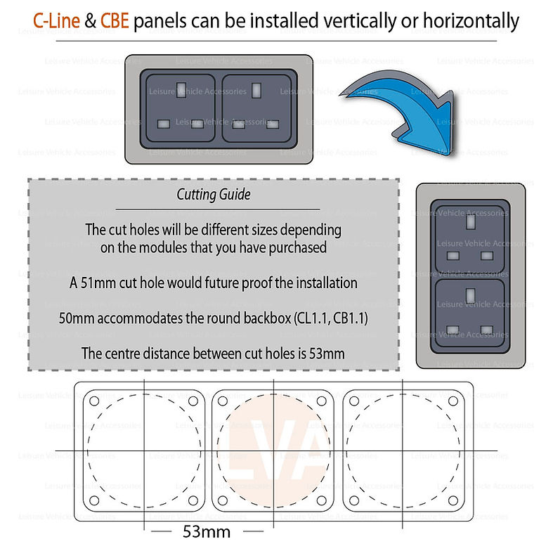
The hole size each module needs varies. We recommend cutting a 50mm hole for every module. It's big enough for any module you might swap in later, and it also accommodates the round backbox (CL1.1 or CB1.1).
For multi-module frames, space the holes 53mm apart, centre to centre.
Panels can be fitted either vertically or horizontally.
Check what's behind the panel before you cut, and keep clear of water pipes and gas lines.
Backboxes (rear covers)
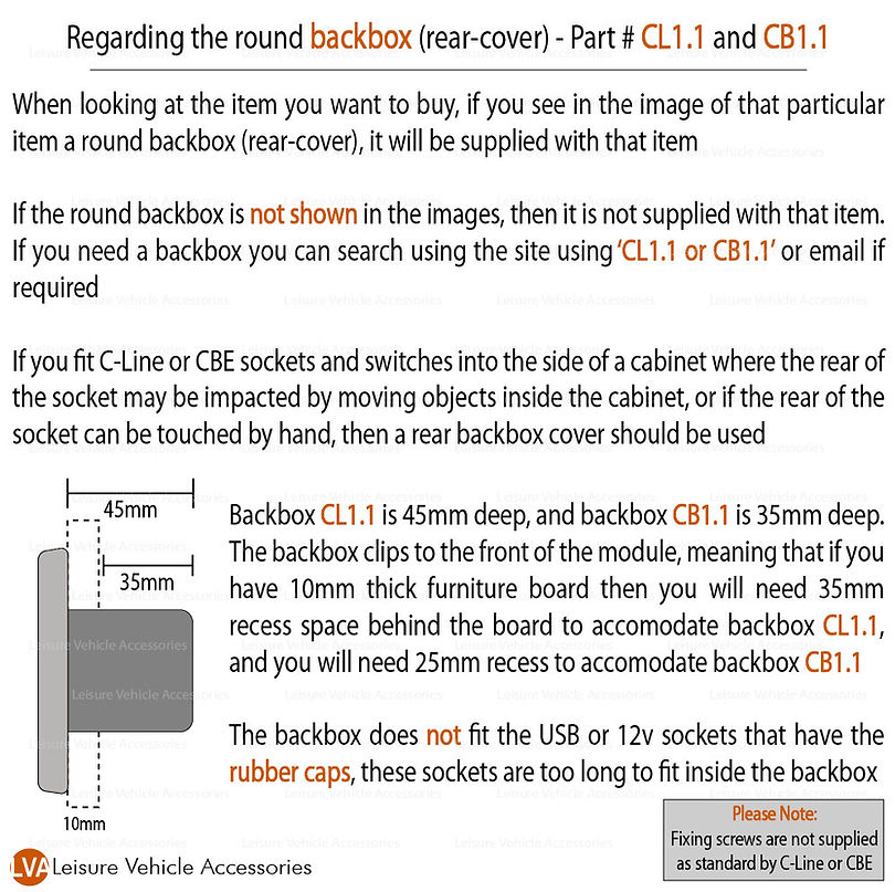
A backbox is a cover that protects the back of the module. Fit one wherever the rear of a socket or switch could be knocked inside a cupboard, or touched by hand.
- A backbox only comes with an item if it's shown in that item's photos. Otherwise, order it separately.
- CL1.1 (C-Line) is 45mm deep. CB1.1 (CBE) is 35mm deep.
- The backbox clips onto the front of the module, so part of its depth sits within the board. On 10mm board you need 35mm of clear space behind the panel for CL1.1, or 25mm for CB1.1.
- Backboxes won't fit USB sockets or 12V sockets with rubber caps, because those modules are too long.
5. Fitting the support frame and outer frame
1. Mark the hole centres, 53mm apart for multi-module frames.
2. Cut 50mm holes and clean up the edges.
3. Feed the cables through, leaving some slack.
4. Wire each module (see the strips below) and tug-test every connection.
5. Clip the modules into the support frame and fix the frame to the panel.
6. Fix with your own screws (not supplied), then clip the outer frame over the top.
7. Reconnect the power and test every switch and socket.
6. Wiring 12V switches, sockets and USB
- Isolate the leisure battery or take the fuse out first.
- Put every 12V circuit through a fuse at the supply end, sized for the cable and no larger than the module's rating. The CBE 4-way fuse module (below) is a tidy way to do this.
- Switch the positive side only, never the negative.
- Use the right connector size: most CBE switches here use 4.8mm blades, and the fuse module uses 6.3mm.
- For cable sizes, follow the product sheet for each part.
7. Wiring 230V sockets and switches
Safety first: 230V mains can kill. We strongly recommend that a qualified electrician fits or tests any 230V socket, switch or fused spur. This guide doesn't replace their work.
- Every 230V circuit must be protected by an RCD and an MCB (or an RCBO) in the consumer unit.
- Unplug the hook-up lead and switch off any inverter before you start.
- Brown is live, blue is neutral and green/yellow is earth. Never leave the earth unconnected.
- Fit a backbox (CL1.1 or CB1.1) behind 230V parts wherever the rear could be touched or knocked. C-Line 230V switches need one.
- After fitting, the installation should be tested.
8. Wiring guides by part
Each strip shows the rear wiring drawing next to a photo of the real part. The drawings aren't to scale and show no dimensions.
CBE 4-Way 12V Fuse Module - SKU: CB2.6
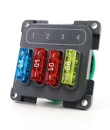
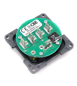
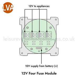
One 12V positive feed to IN +; four fused positive outputs FA1–FA4 on 6.3mm spades. Every terminal is positive, so negatives go back to the battery or chassis. Supplied with 15A, 20A and two 10A blade fuses; module rated 30A total.
CBE 230V 16A Schuko Socket - SKU: CB2.9
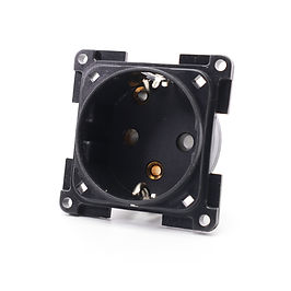
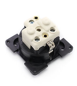
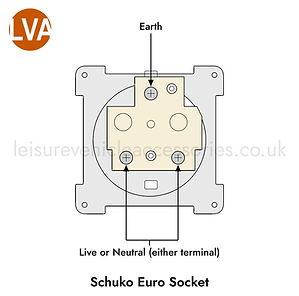
Live and neutral to the two lower screws, earth to the top earth terminal. Feed from an MCB and RCD (or RCBO). 230V: electrician recommended.
CBE Pump and Light Switch - SKU: CB4.5
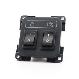
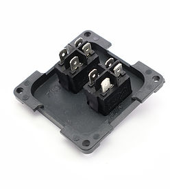
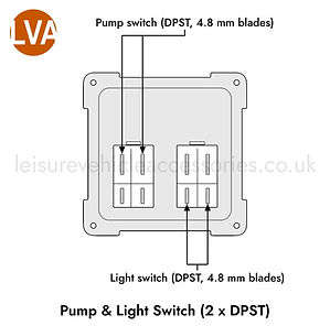
Two separate double-pole on/off rockers (pump left, light right, seen from the rear) on 4.8mm blades. Each needs its own 12V feed; check with a meter which blades form each pole first. Rated 10A per switch